Thursday, 29 March 2012

MAX 232

Week no: week 11 (29/3/2012)

Objective:

  • Function MAX 232
  • Circuit diagram
Content:


MAX 232 is an integrated circuit that convert signal from RS232 serial port to signal suitable for use inTTL compatible digital logic circuit.

The figure above show the simple circuit of the connection between MAX 232 to RS 232 (female)

Thursday, 22 March 2012

RS 232 Cable interface

Week no: week 10 (22/3/2012)

Objective:

  • Research about RS 232
Content:


In telecommunications, RS-232 is the traditional name for a series of standards for serial binary single ended data and control signals connecting between a DTE (Data Terminal Equipment) and a DCE (Data circuit terminating equipment). It is commonly used in computer serial port. The standard defines the electrical characteristics and timing of signals, the meaning of signals, and the physical size and pin out of connectors. The current version of the standard is TIA-232-F Interface Between Data Terminal Equipment and Data Circuit-Terminating Equipment Employing Serial Binary Data Interchange, issued in 1997.
An RS-232 port was once a standard feature of a personal computer for connections to modem, printer, mice, data storage, un-interruptible power supplies, and other peripheral devices. However, the limited transmission speed, relatively large voltage swing, and large standard connectors motivated development of the universal serial bus which has displaced RS-232 from most of its peripheral interface roles. Many modern personal computers have no RS-232 ports and must use an external converter to connect to older peripherals. Some RS-232 devices are still found especially in industrial machines or scientific instruments.

Thursday, 15 March 2012

Current Sensor

Week no: week 9 ( 15/3/2012)

Objective:

  • Current Sensor
Content:
The figure above show the current transducer.

Dimension and connection


Thursday, 8 March 2012

Solar Panel

Week no: week 8 (8/3/2012)

Objective:

  • Solar Panel 
  • Model
Content:

This is solar panel that were purchased.


Model of solar panel 

Thursday, 1 March 2012

Solar cell

week no: week 7 (1/3/2012)

objective:

  • Solar cell diagram
  • Photovoltaic characteristic
Content:


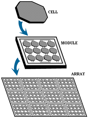
The figure above show the solar panel which cell connected in series and parallel


A solar cell is a solid state device that converts the energy of sunlight directly into electricity by the photovoltaic effect. Assemblies of cells are used to make Photovoltaic module, also known as solar panel. When the solar panel is connected in series the voltage output will increase, while the solar panel connected in parallel the current output will increase. The solar panel connected in series to provide PV panel string, while for PV array is the combination of several PV panel string in parallel connection.


There are two types of PV cell
        i.            Crystalline cells
a.       Monocrystalline ( Single crystalline)
b.      Polycrystalline ( multi crystalline)
      ii.            Thin layer (film) cells
The amount of solar power available per unit area is knows as irradiance. As the irradiance varies there is almost linear variation of the short circuit current. The open circuit voltage however does not change dramatically, it increase slightly as shown in figure below. The graph assumes that the cell temperature is constant, unaffected by the differing irradiance. It is because the voltage remains reasonably constant under varying irradiance solar cell are well suited for use as battery charger.

Thursday, 23 February 2012

Literature Review


Week no: week 6 (23/2/2012)

Objective: 
  • Research from the theory
  • Advantages Solar photovoltaic
Content:


A photovoltaic system is a system which uses solar cells to convert light into electricity. A photovoltaic system consists of multiple components, including cells, mechanical and electrical connection and mountings and means of regulating and modifying the electrical output. Due to the low voltage of an individual solar cell typically 0.5V, several cell are combined into photovoltaic modules, which are in turn connected together into an array.
Photovoltaic power systems are generally classified according to their functional and operational requirements, their components configurations and how the equipment is connected to other power sources and electrical loads. The three principal classifications are grid connected or utility interactive systems, photovoltaic hybrid system and PV stand alone systems. Photovoltaic system can be design to provide DC and AC power service, can operate interconnected with or independent of the utility grid and can be connected with other energy source and energy storage system.

Advantages Photovoltaic 
  • No pollution and totally silent in process energy compare wind and water based from turbine and very noisy 
  • Low cost maintenance and have a long lifetime
  • Not required large space to build. The solar panel can put on the roof top
  • Appropriate to use in Malaysia


GSM technology stands for Global System for Mobile Communication. It is huge, rapidly expanding and successful technology. During the period of evolution of mobile communication technologies various systems were introduced and deployed to achieve standardization in mobile industry but all the efforts were failed. Multiple issues were sustained like incompatibility of systems, development of digital radio frequency. That is when GSM Technology was introduced and problems like standardization incompatibility were overcome.

Advantages GSM
  •                    Uses radio frequencies efficiently and due to the digital radio path, the system tolerates more intercell disturbances.
  •                    The average speech quality is better than analogue system
  •                    Data transmitted throughout the GSM system
  •                     Speech is encrypted and subscriber information security is guaranteed
  •                    International roaming is technically possible within all country using GSM system
  •                   The large market increases competition and lowers prices both for investment and usage


Friday, 17 February 2012

Proposal

week no: week 5 (17/2/2012)

Objective:

  • drafting proposal
  • Research CICB
Content:
  • Abstract & introduction
  • Block diagram of CICB
Result & analysis:

  • The solar energy is an energy from the sun that is converted into thermal or electricity energy.  The amount of energy falling on the earth is given by the solar constant, but very little use has been made of solar energy. The main purpose of the solar energy system as known as renewable energy is to prepare or replace for the depletion of the present source of electricity energy especially coal, oil and gas. It is possible that the world now lacks the source of energy and the world will face a global crisis of cheap oil and recommendations to a decreasing dependency on fossil fuel. This has led to increasing interest in alternate power or fuel research such as fuel cell technology, hydrogen fuel, solar energy, geothermal and wind energy. So the government encouraged to uses the solar energy system in our country in order to overcome the energy crisis in the future. This research knowledge (Development of Solar Photovoltaic Remote Monitoring System) will be hoped to help implementation of the solar technology. Furthermore each renewable energy plant or system plants needs the monitoring control systems. Same as solar photovoltaic system, where the performances and parameters must be closely monitored and controlled, thus allow adequate data acquisition system.  The data acquisition system requires large number of measured data where very frequent recording necessary needs to be automated to eliminate the probability of human error as well as to save time. This project is mainly about computer based real time monitoring system center which use Visual Basic as Graphic User Interface (GUI) to provide graphical display output chart, graph or pie chart. With VB software the solar researcher can be display the measured value from Photovoltaic house. To collect the data from Photovoltaic house to the main computer, the system require interfacing board which consist of microcontroller serial port board. reading measured data, storage data, control the system derive by microcontroller board and to interfacing the microcontroller board through main computer the project use serial port. For the convenience of researcher, the Global System for mobile communication (GSM) technology was attaching in the monitoring system to overcome data transfer. Usually the location of solar photovoltaic is different with the places where we work. So, a remote monitoring system using GSM technology has been used in this research. Beside that, the solar power system can be monitored everywhere.


  • CICB block diagram
Conclusion
  • The diagram show the CICB Block diagram divided to four parts, which is power supply, input, microcontroller and output.

    Power supply:
     Provide +12v +5v -12v -5v and ground power supply to CICB board
    Current transducer:
    to measure current from PV array.
    Op amp circuit:
    The operation amplifier circuit act as amplify the signal voltage from current transducer                       to ADC port PIC 16F877A microcontroller.
    PIC 16F877A:
    Microcontroller will process analog voltage signal from op amp circuit transmit the data to laptop through RS232 circuit and display current and voltage value.

    RS232
    Interface circuit from microcontroller to laptop
    Relay/LED
    Relay is use to control the high voltage 240V by microcontroller and the LED as a indicator for the relay on/off
    LCD
    Display data current and voltage
    Buzzer
    Alarm warning